| |
|
|
| |
|
RTD
Sensors
|
Resistance Temperature
Detectors (RTDs) are one type of temperature
sensors. RTD changes the resistance with
respect to temperature. It measure temperature
because of the physical principle of the
positive temperature coefficient of electrical
resistance of metals. The hotter they become,
the larger or higher the value of their
electrical resistance.
The RTD element consists of a thin film
of platinum or nickel which is deposited
onto a ceramic substrate and laser trimmed
to the desired resistance. Thin-film elements
attain higher resistances with less metal
and, thus, tend to be less costly then the
equivalent wire-wound element. RTDs also
called resistance thermometer.
Resistance thermometers require a small
current to be passed through in order to
determine the resistance. This can cause
resistive heating, and manufacturers' limits
should always be followed along with heat
path considerations in design. Lead wire
resistance should be considered, and adopting
three and four wire connections can eliminate
connection lead resistance effects from
measurements. Industrial practice is almost
universally to use 3-wire connection. 4-wire
connection needs to be used for precise
application.
Some metals have a very predictable change
of resistance for a given change of temperature.
A precision resistor is made from one of
these metals to a nominal ohmic value at
a specified temperature. By measuring its
resistance at some unknown temperature and
comparing this value to the resistor's nominal
value, the change in resistance is determined.
Because the temperature vs. resistance characteristics
are also known, the change in temperature
from the point initially specified can be
calculated.
|
| |
Common
Resistance Materials for RTDs
|
• Platinum
(most popular and accurate)
• Nickel
• Copper
• Balco (rare)
• Tungsten (rare)
|
| |
What
are the parameters to select a right RTD
sensor?
|
• Sensor
material
• Temperature coefficient
• Nominal resistance
• Wiring configuration
|
| |
Temperature
Range
|
Platinum RTD's
can measure temperatures from -200°C
to 650°C. You must consider the temperature
limitations of all the materials involved,
where they are applied, and the temperatures
to which each will be exposed.
|
| |
Temperature
Coefficient
|
The temperature
coefficient (TC), or alpha of an RTD is
a physical and electrical property of the
metal alloy and the method by which the
element was fabricated. The alpha describes
the average resistance change per unit temperature
from the ice point to the boiling point
of water.
RTDs are manufactured from metals whose
resistance increases with temperature. Within
a limited temperature range, the resistivity
increases linearly with temperature. Each
metals specific, and unique resistivity,
can be determined experimentally. This resistance
is directly proportional to a metal wire's
length, and inversely proportional to the
cross-sectional area.
R = k L / A
where
R = resistance (ohm, O)
k = constant of proportionality or resistivity
of the material (ohm, O)
L = length of conductor (m)
A = cross sectional area of conductor (m2)
Resistivity and temperature can be expressed
as
kt = ko [1 + a (t - to)]
where
kt = resistivity at temperature t (ohm,
O)
ko = resistivity at standard temperature
to (ohm, O)
a = temperature coefficient of resistance
(1/oC)
t = temperature (oC)
to = standard temperature (oC)
|
Resistance
thermometer elements
|
Resistance thermometer
elements are available in a number of forms.
The most common are:
• Wire wound in a ceramic insulator
- wire spiral within sealed ceramic cylinder,
works with temperatures to 850 °C
• Wire encapsulated in glass - wire
around glass core with glass fused homogenously
around, resists vibration, more protection
to the detecting wire but smaller usable range
• Thin film - platinum film on ceramic
substrate, small and inexpensive to mass produce,
fast response to temperature change
|
| |
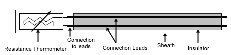
Resistance
thermometer construction
|
|
These elements
nearly always require insulated leads attached.
At low temperatures PVC, silicon rubber
or PTFE insulators are common to 250°C.
Above this, glass fiber or ceramic are used.
The measuring point and usually most of
the leads require a housing or protection
sleeve. This is often a metal alloy which
is inert to a particular process. Often
more consideration goes in to selecting
and designing protection sheaths than sensors
as this is the layer that must withstand
chemical or physical attack and offer convenient
process attachment points.
|
| |
Resistance
thermometer wiring configurations
|
Two-wire
configuration
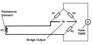
The simplest resistance thermometer configuration
uses two wires. It is only used when high
accuracy is not required as the resistance
of the connecting wires is always included
with that of the sensor leading to errors
in the signal. Using this configuration
you will be able to use 100 meters of cable.
This applies equally to balanced bridge
and fixed bridge system.
Three-wire configuration
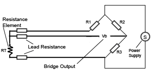
In order to minimize the effects of the
lead resistances a three wire configuration
can be used. Using this method the two leads
to the sensor are on adjoining arms, there
is a lead resistance in each arm of the
bridge and therefore the lead resistance
is cancelled out. High quality connection
cables should be used for this type of configuration
because an assumption is made that the two
lead resistances are the same. This configuration
allows for up to 600 meters of cable.
Four-wire configuration
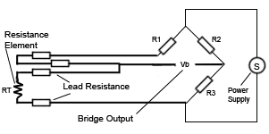
The four wire resistance thermometer configuration
even further increases the accuracy and
reliability of the resistance being measured.
In the diagram above a standard two terminal
RTD is used with another pair of wires to
form an additional loop that cancels out
the lead resistance. The above Wheatstone
bridge method uses a little more copper
wire and is not a perfect solution. Below
is a better alternative configuration four-wire
Kelvin connection that should be used in
all RTDs. It provides full cancellation
of spurious effects and cable resistance
of up to 15 O can be handled. Actually in
four wire measurement the resistance error
due to lead wire resistance is zero.
|
SPECIFICATION
|
Range: -220
to 850°C for platinum RTDs and -200
to 340°C for Nickel RTDs
Linearity: Platinum and copper are more
linear. Nickel and Balco are less.
Sensitivity: -10 to 100 ohms/degree
|
| |
Advantages
|
• High accuracy
• Low drift
• Wide operating range
• Suitability for precision applications
• Stable output for long period of time
• Ease of recalibration
• Repeatability
• Not affected by the corrosion or oxidation
|
| |
Limitations
|
• RTDs
in industrial applications are rarely used
above 660 °C. At temperatures above
660 °C it becomes increasingly difficult
to prevent the platinum from becoming contaminated
by impurities from the metal sheath of the
thermometer. So that laboratory standard
thermometers replace the metal sheath with
a glass construction. At very low temperatures,
say below -270 °C (or 3 K), there are
very few phonons, the resistance of an RTD
is mainly determined by impurities and boundary
scattering and thus basically independent
of temperature. As a result, the sensitivity
of the RTD is essentially zero and therefore
not useful.
• Compared to thermistors, platinum
RTDs are less sensitive to small temperature
changes and have a slower response time.
However, thermistors have a smaller temperature
range and stability.
|
| |